The intent of this technical note is help to the user to know the elements that are part of the
electrical circuit of a load cell. First of all, we will show the basic working circuit of a load cell,
based on a Wheatstone bridge and strain gauges; afterwards, we will complete the circuit for a
real load cell, where it is necessary an additional circuitry that allows obtaining a high precision
sensor.
Basic circuit: The Wheatstone bridge
A load cell is based on an electrical circuit called Wheatstone bridge.
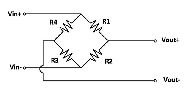
Being Vin the power supply of the bridge or input excitation (V=Volts) and Vout the output signal
(mV=milivolts).
This arrangement allows to measure very small changes in the resistance ∆R, which occurs in the
strain gauges placed in the arms of the bridge: R1, R2, R3 and R4.
Strain gauges are deformation sensors which are glued to the elastic body of the load cells. An effort that deforms the
gauge will produce a change ∆R in its nominal resistance value Rg. This small resistance change on
each gauge is magnified by the resistive imbalance produced in the Wheatstone bridge and thus
obtains an output signal proportional to the applied force.
When the load cell has no load, the four gauges are at rest and have the same ohmic value, the
nominal value of the strain gauge Rg:
R1=R2=R3=R4=Rg
Then, the output signal Vout, differential between Vout+ and Vout‐, is 0 Volt (zero of the load cell).
When loading the load cell, the strain gauges changes its resistance value in a very small ratio ∆R:
R1=Rg‐∆R ; R2=Rg+∆R ; R3=Rg‐∆R ; R4=Rg+∆R
Then, we will obtain an output signal Vout, proportional to the resistance variation of the strain
gauges. This is at the same time proportional to the deformation of the elastic body of the cell,
which is proportional to the applied force. Thereby obtains a force transducer with an electrical
output signal proportional to the applied force.
Should be noted, that this resistive circuit it is also proportional to the input voltage supply, so the
output of the load cell it is usually expressed in mV/V, milivolts per volt (supply).
Complete circuit for a high precision load cell
To manufacture a real high precision load cell, it is necessary an additional circuitry to the strain
gauges, dedicated to the fine adjustment of the output signal at different loads and also to make
the necessary individual thermal compensations during the manufacturing process.
The following wiring diagram allows us to identify different stages, described below.
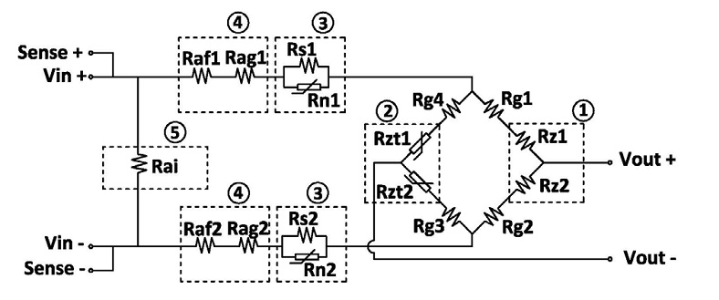
1 . Rz1 a Rz2
Zero balance resistors. We perform a fine adjustment of the output signal without load
(zero of the cell) to get a value very close to 0mV.
2. Rzt1 a Rzt2
Zero shift temperature compensation resistors. We perform fine adjustments with small
thermal compensation resistors to get a stable zero signals with temperature.
3. Rs1, Rn1 a Rs2, Rn2
Sensitivity compensation resistors with temperature. Resistors Rn1 and Rn2, change their
nominal resistance value with temperature, Rs1 and Rs2 are used to compensate the
changes produced in the mechanical elasticity of the load cell’s body to obtain a total gain
stable with temperature.
4. Raf1, Rag1 a Faf2,Rag2
Sensitivity adjustment resistors. Rag resistors are used to perform the coarse adjustment
and Raf resistors are used for the fine adjustment of the nominal sensibility value (Sn) of
each load cell in mV/V.
5. Rai
Input impedance adjustment resistor. It is used to get an input impedance load cell value
within the specifications range.
The output signal Vout of a load cell at Nominal Capacity (Ln) is described by the Nominal
Sensitivity (Sn) and the power supply (Vin).
Nominal Sensitivity (Sn, in mV/V) is the increase of the output signal (Vout, in mV) when it is
applied an increase in force equal to the nominal capacity (Ln, kg), in relation to the supply voltage
(Vin, in V).
As an example we describe a load cell of 100kg Nominal Capacity (Ln) and Nominal Sensitivity
(Sn) of 2mV/V. This means that the output signal will increase in 2mV, for each supplied V, when it
is applied an increase of load equal to 100kg. Also, this increase is lineal and proportional to the
applied load. In the case of a supply voltage of 10V, then we will obtain from 0 to 100kg of load
and output from 0mV to 20mV of signal.